Compressed air system for auxiliary engines on board performs some critical functions -starting,stopping & pneumatic controls

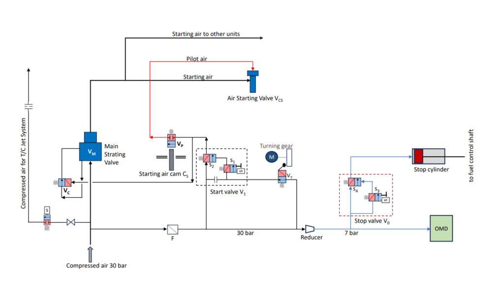
Figure 1. Starting & Control Air System

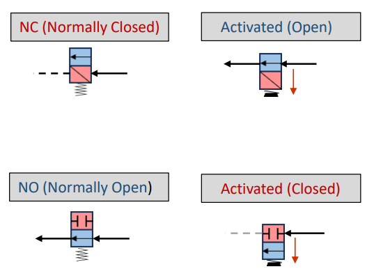
NC (Normally Closed) valve will remain closed when not activated,as shown.However,whenever activated or energized the valve spool will be pushed against the spring in the direction of the arrow and open.
NO (Normally Open) valve will remain open when not activated,as shown.However,whenever activated or energized the valve spool will be pushed against the spring in the direction of the arrow and closed.
Figure 1 above represents simplified diagram of the starting & pneumatic control system for 4-stroke auxiliary engines on board.Compressed air at approximately 30 bar is supplied to the system.Part of the supply is reduced to 7-8 bar by a reducer,R for various control functions.
Main components of the system
- Main starting valve,VM
- Control valve for main starting valve,VC
- Air starting valves,VCS (located at each cylinder head)
- Starting air pilot valves,VP (located beside each fuel injection pump)
- Starting air cams,CS
- Start valve,V1 (combination of valves, s1 & s2)
- Stop valve,V0 (combination of valves, s3 & s4)
- Turning gear interlock valve with limit switch,VT
- Filter,F
- Reducer,R
- Stop cylinder
- Oil mist detector (OMD)
Starting
Starting air passes through Main starting valve before reaching cylinder Air starting valves.However,the cylinder Air starting valve will not open until pilot air from corresponding Pilot air valve is delivered to the valve & pushes it open.
Main Starting air control valve,VC normally remains open.Compressed air at 30 bar from the system through the valve VC works on the Main Staring air valve,VM in the reverse direction of opening and,therefore,counter-act opening of the valve VM.
In addition,Main Staring valve,VM is fitted with a powerful closing spring.Thus, combined action of the closing spring & the compressed air through the valve VC ensures positive closing of VM when not activated.
In reference to the diagram above,whenever engine start command is given – start solenoid valve V1 is activated(valve s1switched to open).If turning gear is disengaged compressed air through valve VT will pass through the valve s1 & depress valve s2 open.This will,in turn,allow control air to reach till the Starting Air pilot valves,VP & the Control Valve for main starting air valve,VC
Valve VC which normally remains open, is now the pushed to close against spring force.This closure results in venting of the chamber filled with the compressed air counteracting opening of the Main Staring air valve,VM.Valve VM is now opened by 30 bar air overcoming the closing spring. Staring air reaches & remain stand-by at the inlet of the Cylinder Air starting valves,VCS fitted on each cylinder head Cylinder Air starting valve,VCS will be opened by pilot air from the corresponding Starting air pilot valve VP.Opening of the VP is actuated by staring air cam based on timing & firing order of the cylinders.
Stopping
During stoppage,Stop valve,V0 (combination of valves, s3 & s4) is activated (switched to open) by the stop signal from the control system.Control air at 7 bar is led through the V0 (valves, s3 & s4) to stop cylinder.Control air pushes stop piston outward – Fuel oil control shaft as well as fuel racks are forced to zero index.
Both the Start valve,V1 and the Stop valve,V0 can be activated manually at the engine side by depressing a push button incorporated with the valves.
In addition to above – compressed air at 30 bar is supplied to T/C jet assist system through solenoid valve & orifice for initial acceleration of T/C during starting.
And compressed air at 7 bar is supplied through reducer for OMD for operation.
the end.