CW system for 4-stroke Auxiliary Engines on board
The cooling water systems of modern 4-stroke auxiliary engines are,basically,a combination of two circuits:
I. A low temperature (LT) circuit, and
II. A high temperature (HT) circuit
Further,it needs to be noted that the CA (charged air) coolers in the system are having two stages: Stage 1 & Stage 2.
Stage 1 – circulated by the HT cooling water.Cools down CA cooler (stage 1),cylinder liners & cylinder heads.
Stage 2 – circulated by the LT cooling water.Cools down CA cooler (stage 2),lubricating oil cooler and the alternator heat exchanger (in some designs).
Cooling water system configuration
1-string system – in this system HT circuit & LT circuit are interconnected.The attached HT cooling water pump draws suction from the LT circuit discharge.There is no separate HT cooling water cooler.The outlet of HT water circuit is directed to & joins the LT water circuit outlet,and both HT & LT circuit utilize vessel’s LT FW system cooler for heat dissipation(ref. to Fig. 1 below).
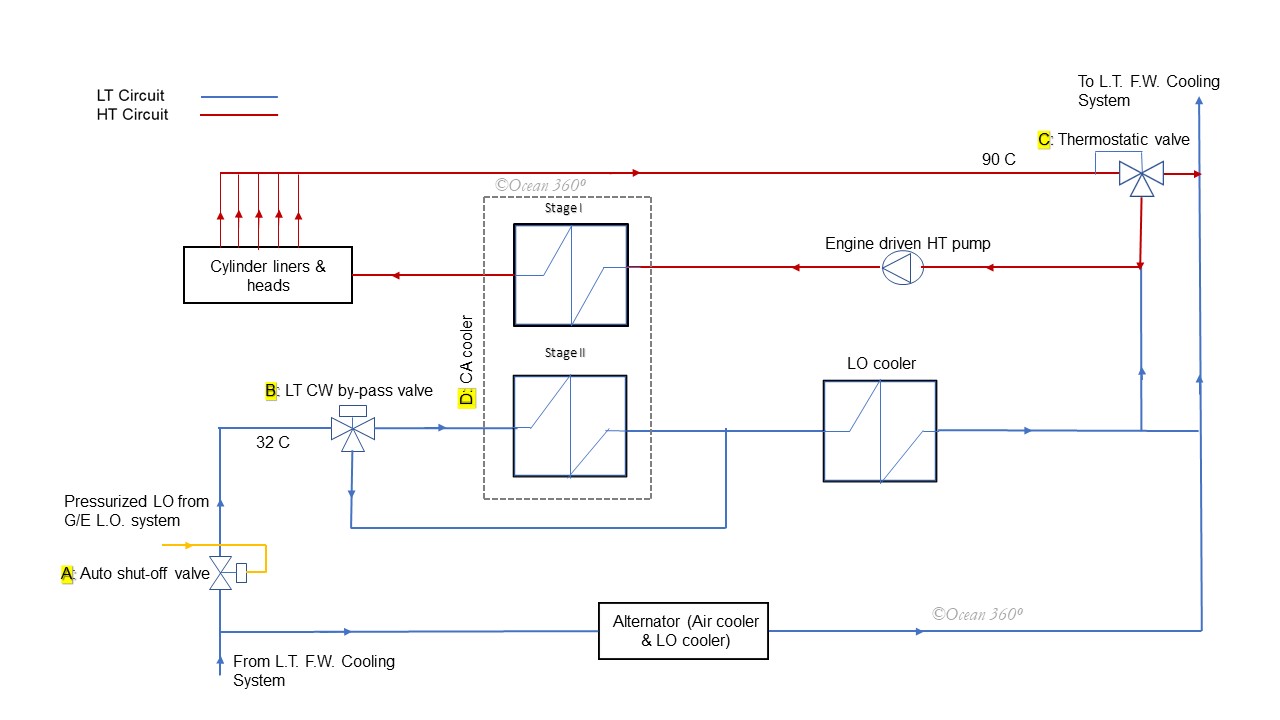
Fig.1 Typical CW system(1-string)
2-string system – in this system LT circuit and HT circuit are not interconnected,both systems are standalone.The system requires an additional heat exchanger/cooler for the HT circuit(ref. to Fig. 2 below)
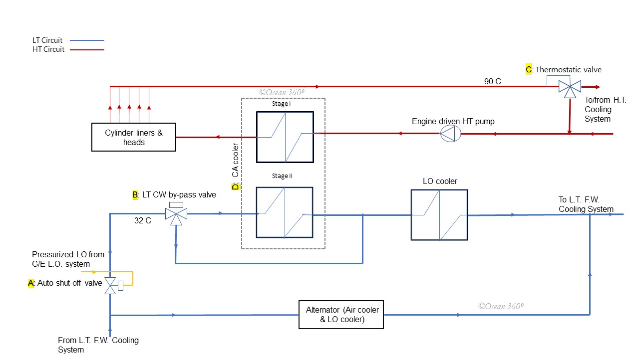
Fig.2 CW System(2-string)
In reference to the Fig.1 & the Fig. 2 above:
A: Automatic Shut-off valve – controls the flow of cooling water to the LT circuit.This valve is opened hydraulically by pressurized lube oil from the engine L.O. system.Whenever engine is started and L.O.pressure builds up the valve is opened by LO pressures as shown in the diagrams above.The valve shuts-off and interrupt cooling water flow whenever engine is stopped and L.O. pressure drops.
B: 3-way, electric/pneumatic by pass valve – As mentioned earlier,in case of low-load running of the engine,CA cooler stage 2 is by-passed and CW is diverted directly to L.O. cooler.Generally,switch over point is set at 20% load.Up to 20% load, this 3-way valve remains energized and by-pass active.Above 20% load valve is de-energized and by-pass shut-off, directing CW flow the CA cooler stage 2.
Low Temperature(LT) Circuit
Cooling water from vessel’s L.T. F.W. cooling system,set ideally at 32 °C ,in the first place passes through the CA cooler(stage 2),thereafter through the LO cooler.In case of low engine load,stage 2 is by-passed,and diverted directly to LO cooler.After LO cooler,cooling water flows partly to the suction side of HT pump (for HT circuit) and partly back to the vessel’s L.T. system Cooler (Central cooler).
Additionally,a branch of LT cooling circuit passes through Alternator heat exchanger/cooler for Alternator cooling.
High Temperature(HT) Circuit (1-string)
In reference to Fig.1 above:
The system includes an engine-driven HT cooling water pump and a 3-way thermostat valve.HT Pump draws from LT circuit discharge as well as 3-way thermostatic valve by-pass side.Pump circulate HT cooling water through CA cooler stage1,cylinder liners and finally through cylinder heads. Ideally,engine discharge is maintained nearly 90 °C.Engine discharge temperature is continuously monitored and fed back to C: 3-way thermostatic valve,which regulates the discharge either to the cooler or back to the HT pump suction on the basis of the feedback to maintain desired temperature at the engine outlet.
High Temperature(HT) Circuit (2-string)
In reference to Fig. 2 above:
As mentioned earlier,in case of 2-string HT circuit only difference is that LT & HT circuits are not interconnected,rather independent.Here HT cooling water pump takes suction from and discharges to the vessel’s common HT system,and there is a separate HT cooler for cooling.
–the end.