Water carry-over is the most significant factor for cylinder liner wear & cold corrosion
Combustion air (Scavenge air,Charge air) drawn in from the surrounding by the Turbocharger passes through the Air Cooler for cooling down.This cooling down increases density as well as mass of the air supplied to the engine cylinders and ensures that there is adequate combustion air for complete combustion of the fuel supplied to engine cylinders.
However,cooling down of combustion air leads to condensation of moisture content in the air & water carry-over along with the air.And this condensation is very common whenever vessel transits areas where humidity of air is high.
Water carry-over into the engine cylinders is extremely harmful and is the principal cause of cylinder liner wall oil film breakdown and cold corrosion.
Impacts of water(condensate) carry-over
The most significant impacts of water(condensate) carry-over are:
- Breakdown of oil film between piston rings and cylinder liner
- a breakdown in oil film may cause scuffing,blow-past,scavenge fire and increased liner wear
- Formation of Sulphuric acid in the combustion space
- Sulphuric acid formation inside engine will lead to cold corrosion and significantly reduce the life of cylinder liners and associated engine components
- Poor combustion,black smoke and reduced thermal efficiency
Countering Water Carry-Over
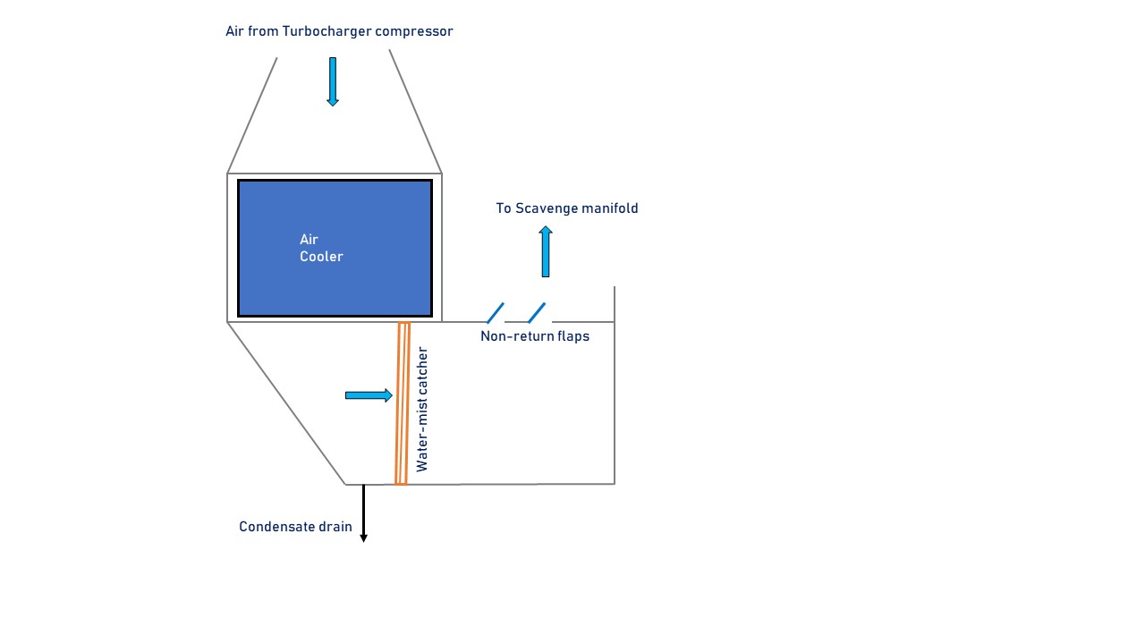
Watermist catchers or condensate separators are installed after Air Coolers to remove water vapour or condensate from combustion air.

Fig.1 Watermist catcher fitted in 2-stroke Main Engine
Fig.1 shows the location of watermist catcher after the the Air cooler of a typical 2-stroke engine.

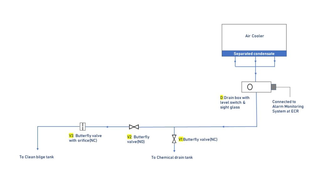
Fig.2 Typical arrangement for automatic & continuous removal of M/E Air Cooler condensate
Fig. 2 above represents a typical arrangement for modern 2-stroke Main engine for automatic & continuous removal of condensate from the bottom of the Air cooler.
As shown in the Fig. 2,the system is having a drain box (D) and three butterfly valves (V1,V2 & V3).
V1 & V3 are NC (normally closed) and V2 is NO (normally open).Valve V3 is of special design and having an orifice (dia 10-20 mm) in the disc.Hence,V3 allows a regulated quantity of condensate passage even when fully closed.To remove excessive accumulation V3 can be opened fully for full flow.
Drain box (D) is fitted with a sight glass & a float.Condensate will pass through this chamber before draining out.In case of abnormal condensate quantity,the float will be lifted and an alarm will be triggered.
It is imperative to investigate activation of any alarm.As Air Cooler tube leakages or similar kind of breakdown will also trigger an alarm.

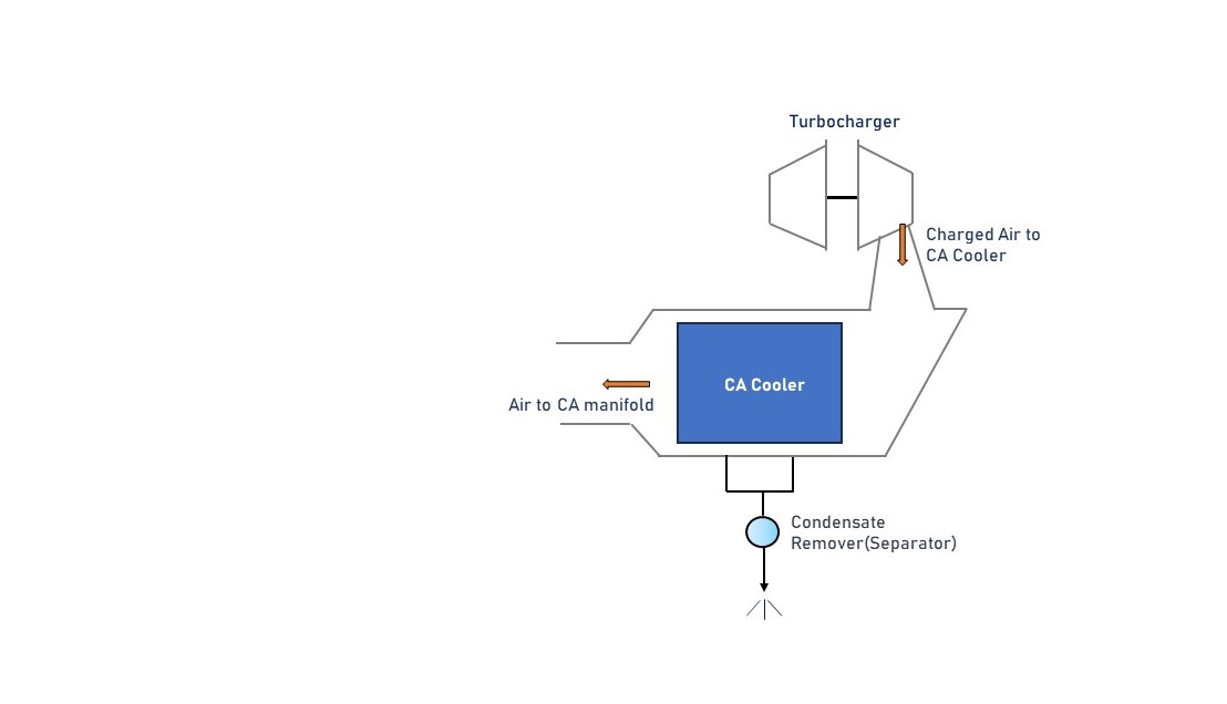
Fig.3 Condensate Separator in 4-Stroke Engine
Fig. 3 represents automatic condensate drainage arrangement fitted with 4-stroke Auxiliary engine.A float operated valve fitted in the drain passage is opened and closed for this function.
Whenever the float chamber is flooded with condensate it lifts up the float and opens the drain valve.The float drops down and closes the valve when there is no or insignificant condensate.
-the end.