Works on the principle of vapour compression refrigeration system
Refrigerant & Temperature Settings
Refrigerant(typically used on board contemporary vessels): R 407C
Set temperatures for cold rooms (Meat room & Fish room): -18 C
Set temperature for chilled room (Vegetables room): 4 C
Working Principle & System Components
The provision refrigeration plant on board works on the principle of vapour compression refrigeration cycle.And cooling of the cold chambers are achieved through heat exchange between refrigerant (cooling medium) and cold chamber atmosphere(circulating air) at the evaporator.
Principal components of a typical provision refrigeration system on board are as follows:
- Compressor
- Condenser
- Expansion valve
- Evaporator
- Oil separator
- Filter drier
- Heat exchanger
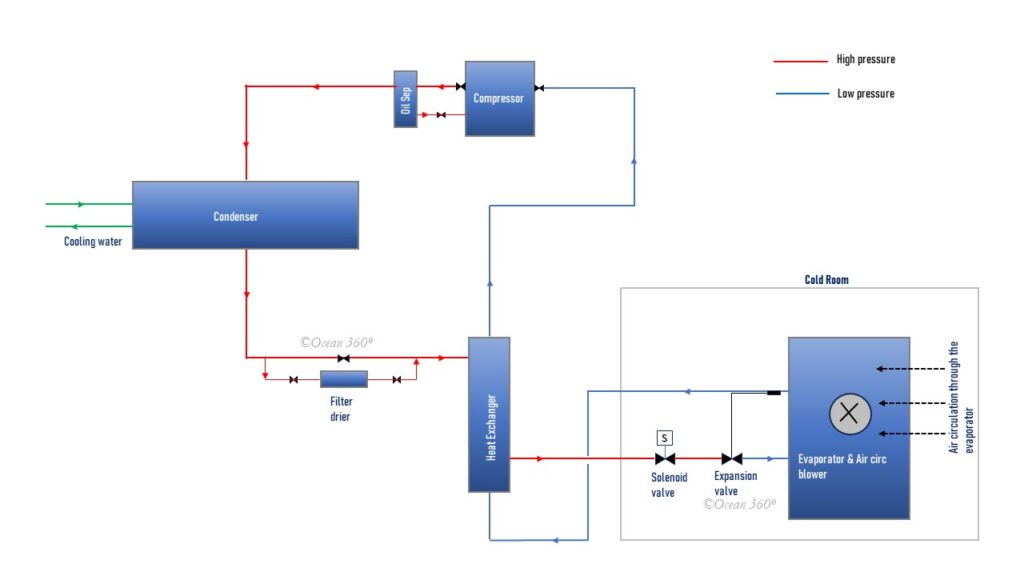
Fig.1 Provision Refrigeration System
Compressor
Compressor is the core component of any refrigeration system and is driven by an electric motor.It draws in low pressure refrigerant from the evaporator discharge side.Ideally,the refrigerant leaving the evaporator and entering the compressor should be in gaseous state & superheated.
At compressor the refrigerant is compressed and discharged at much higher.This significant enhancement of pressure of the refrigerant at the compressor causes:
- Condensation temperature of the refrigerant leaving the compressor to be elevated.As result the refrigerant can be condensed or liquefied at much higher temp at the condenser,for instance at 35 C temperature.
- This is because –the higher the pressure, the higher the condensation temperature
- Circulation of the refrigerant through out the system
Condenser
At condenser gaseous refrigerant discharged from the compressor at high temperature & pressure,is condensed & liquefied.
Cooling Water (at about 30 C) from the central cooling system is widely used as condenser coolant.
Thermostatic Expansion Valve(TEV)
TEV is the interface between the high-pressure side and the low-pressure side of the system.
High pressure liquid refrigerant,roughly at 18 bar,is throttled to a significantly lower pressure.Low enough to reduce the evaporation temp of the refrigerant to fall to somewhere around – 24 C.The lower the pressure, the lower is the evaporation temperature.
Expansion valve also act as a regulator to inject correct quantity of refrigerant into the evaporator coils.
ideally, refrigerant should leave Evaporator with some degree of superheat,about 5-7 C.This superheating will ensure refrigerant at the compressor suction is fully in gaseous state and prevent compressor damage due to carry over of liquid refrigerant.
At TEV,high pressure liquid refrigerant passes through a very tiny orifice which is thermostatically controlled.A sensor bulb fitted at the outlet side of the evaporator monitors the degree of superheat in the refrigerant leaving the evaporator coil,and controls the opening of the orifice accordingly.For higher degree of superheat opening of the orifice will be increased resulting in more flow of refrigerant and for lower superheat opening of the orifice will be reduced resulting in less flow of refrigerant.
Evaporator
Each cold room (cold chamber) is fitted with an evaporator and an associated circulation fan unit.Before entering the evaporator coil refrigerant passes though a solenoid valve & an expansion valve,as shown in the Fig.1 above.
Circulation Fan associated with the Evaporator draws air from the surrounding and blows the drawn in air through the fins of the coils externally.
This results in heat exchange at the Evaporator between the air circulated externally and the refrigerant passing through the coils internally.Low pressure liquid refrigerant having an evaporation temp,as low as -24 C,in that state,as mentioned earlier,keeps absorbing heat from the air & continues to evaporate to dry gaseous refrigerant until the cold room temp drops to the preset temp,say -18 C,and the room solenoid valve closes to interrupt the refrigerant flow.
Oil Separator
Fitted next to the compressor.It removes & redirects oil particles,carried over along with the refrigerant from the compressor,back to the crankcase.
Filter Drier
Removes moisture content & traps dirt particles contained in the refrigerant.
Solenoid Valve
Each cold room(cold chamber) is fitted with a solenoid valve.
Solenoid valve control the flow of refrigerant to evaporator fitted in each room.
Heat Exchanger
Fitted between condenser discharge & compressor suction.
Low pressure & temperature (about -18 C) refrigerant leaving the evaporator passes internally through the heat exchanger tubes before entering the compressor suction side, while the high pressure & temp (> 20 C) liquid refrigerant leaving the condenser circulates externally surrounding these passages.The large temp differential between the two streams of the refrigerant results in heat exchange and ensures any liquid content in the refrigerant after the evaporator is converted into gas before entering the compressor.
Automatic Operation
Figure 1 represents a typical provision refrigeration system on board.Arrows indicate direction of flow of the refrigerant.As indicated,red lines represent the high pressure part and the blue lines represent the low pressure part of the system.
Starting and stopping of the compressor is initiated by the low-pressure controller.For instance, for a compressor cut-out is set at 0.4 bar and cut-in at 1.4 bar.
Each cold room(chamber) is fitted with a solenoid valve & a thermostatic expansion valve.As long as the temperature of a cold rooms is above the set point the solenoid valve remains energized (open).Solenoid valve closes whenever the temperature of the cold room reaches the set point,say -18 C,for a cold room.Closing of the solenoid valve interrupts the refrigerant flow to the evaporator for that particular cold room,and ultimately leads to reduction of refrigerant flow to suction side of the compressor.
Due to cooling down of all cold rooms to the set temperature over time,all room solenoid valves start to close one after another.At one stage,all room solenoid valves will be de-energized (closed) and flow of refrigerant will be totally interrupted.There will be significant pressure drop at the suction side of the compressor.Suction pressure falling to the cut-off point,say 0.4 bar,and will stop the compressor.
Cold rooms temperatures will gradually rise in this state.Solenoids will reopen and allow flow of the refrigerant through the system.This,in turn,will increase the pressure at the suction side of the compressor.At 1.4 bar,for instance,the compressor will restart and the cycle will be repeated.
Safety Devices
- Combined High & Low pressure control (pressure switch).
- High pressure compressor cut out – set at about 18 bar(adjustable).
- to be reset manually
- Low pressure compressor cut in /cut out (adjustable). Cut in set at about 1.4 bar and cut out set at about 0.4 bar
- High pressure compressor cut out – set at about 18 bar(adjustable).
- Oil pressure control
- Compressor cut out at about 0.9 bar.
- to be reset manually
- Compressor cut out at about 0.9 bar.
- Condenser CW low pressure trip
- Compressor motor overcurrent trip
Anti-Recycling
To protect the compressor motor from overheating & the subsequent damage,some built-in timer relay is fitted in the starter circuit.Once motor cuts out,it will restart only after certain preset time,for instance 300 seconds.This ensures adequate cooling interval for the motor between two consecutive starts.
Leak Detection Unit
Fitted in the vicinity of the compressor area.It triggers an alarm in case of refrigerant leakage.
Defrosting
Formation of ice takes place on evaporator coils during operation.
Icing impedes circulation of air through fins on the evaporator coils.This results in reduced heat exchange between the cooling medium (refrigerant) and the atmosphere of the cold room.
Eventually,the performance of the plant falls significantly.
Electrical heating elements are generally fitted for defrosting or removal of the ice on the evaporator coils.
At preset intervals compressor is stopped & cold rooms solenoid valves are de-energized automatically.After that,air circulation fans of the evaporators switched off.
Then heating elements are energized for defrosting.
Whenever the evaporator coils surface temperature reach the preset value,electrical heating is switched off and the system is restarted in sequence.
–the end.
Excellent explanation sir. Thanks.