A rotary cup burner utilizes centrifugal force for atomization & propagation of fuel oil inside the furnace.This system is having :
- a Primary/Ignition burner,and
- a Main burner
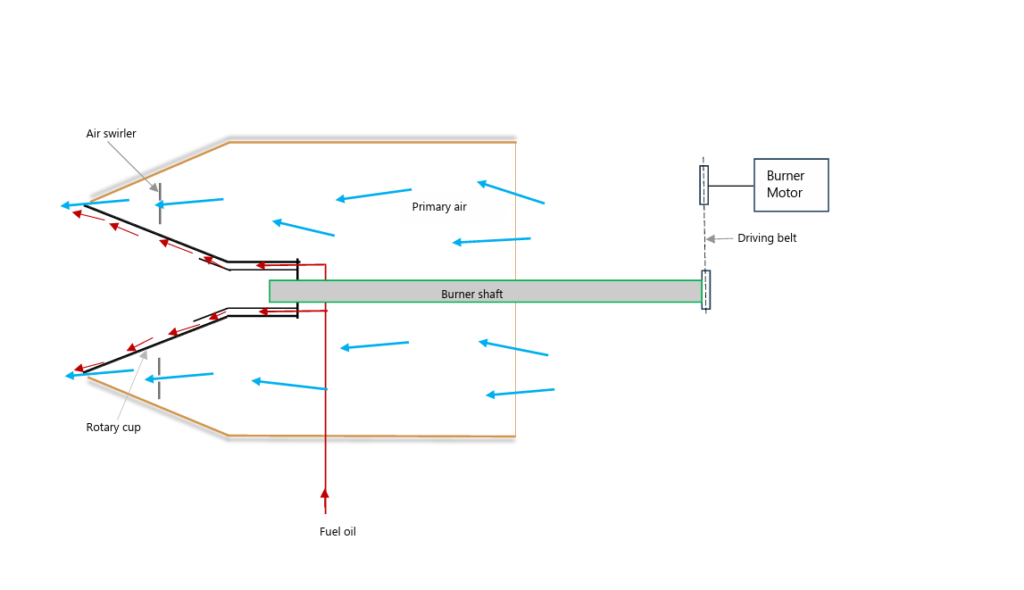
Figure 1 – Rotary Cup Burner
Primary/Ignition burner
The Ignition burner,as its name implies initiates the ignition and needs an external source for the purpose.Two high voltage electrodes with precise gap in between,are fitted at the tip of the burner.A high voltage ignition transformer creates arching between the electrodes,and generates high energy electrical spark.Atomized distillate fuel (MDO,MGO etc.) injected from the burner nozzle is ignited by the spark and establish the primary flame.
Main burner
The central component of the main burner is a cone shaped cup,known as rotary cup that spins at a high speed and is driven by an electric motor.
Fuel oil from the Main burner is sprayed on to a high speed rotary cup through a specially profiled nozzle.Centrifugal force imparted to the fuel droplets breaks down the droplets further into finer particles and pushes into the furnace.
High-velocity primary air with powerful turbulence entering from the outer edge of the rotary cup interact with the forward moving cone of fine fuel particles and creates a uniform mist of air-fuel mixture.To ensure availability of adequate supply of air for complete combustion of the supplied fuel,forced draft (FD) fan supplies secondary/combustion air through the air register.
The air-fuel mist created at the main burner is then ignited by the primary flame established by the Ignition burner.
Automatic Combustion Control
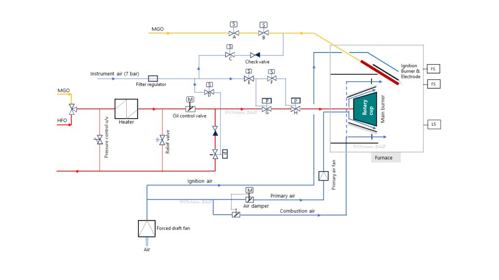
Figure 2 – Rotary Cup Burner System
Legend (Figure 2)
- A,B,C,D,E & F : Solenoid valve
- G,H & I : Pneumatically actuated valve
- FS : Flame scanner
- LS : Limit switch (for burner swing out)
In reference to the Fig.2,whenever firing sequence is initiated,purging of the furnace for a preset duration is carried out in the first place.Burner controller then energizes (opens) solenoid valves – A & B,enabling distillate fuel (MDO/MGO) to flow through the valves to the Ignition burner and,finally,being injected through the nozzle in the form of fine mist.This mist is ignited by the spark generated by the electrodes and primary flame is established.
After certain preset interval (few seconds),the burner controller de-energizes (closes) solenoid valve D,and energizes (opens) solenoid valves E & F.
Closing of solenoid valve D interrupts control air flow to the pneumatically actuated fuel oil recirculation valve I,as result valve I closes.On the other hand,opening of solenoid valves E & F,leads control air to the corresponding pneumatic fuel shut off valves- G & H.Now fuel shut off valves G & H are open.
Pressurized fuel oil delivered by FO supply pump passing through the heater,the fuel oil control valve,and valves – G & H,finally reaches the main burner nozzle.
Main burner nozzle breaks up fuel into tiny droplets and sprays on to the inner surface of the rotating cup.At rotating cup further atomization of fuel takes place due to the combined action of the rotating cup and the turbulent primary air.
The main function of the primary air supplied through the narrow passage at the outer edge of the rotating cup is to create turbulence so that fuel particles leaving the rotating the cup is broken down further to finer particles and prepare an evenly mixed air-fuel mist.Additionally,to ensure availability of adequate supply of air for complete combustion of the fuel,secondary air is supplied.
Oil-fuel mixture is then ignited by the primary flame already established by the Ignition burner.Main burner continues to burn fuel as long as no shut down signal is transmitted from the burner controller.
However,Ignition burner is cut off after a preset interval from the commencement of primary ignition.When the preset interval elapses solenoid valves – A & B,are de-energized (closed) and fuel supply to the Ignition burner is stopped.At that time,solenoid valve C is opened and compressed air is blown through the burner to remove all traces of oil.This purging continues as long as secondary (main) flame is present.The purging arrangement is an additional safety measure to prevent explosion resulting from light oil leakages through the burner or valves.In addition,a flame scanner is included for the Ignition burner to monitor the flame.
During shutting down,the burner controller energizes(opens) solenoid valve C which in turn opens pneumatic recirculation valve I,and de-energizes(closes) solenoid valve D & E which in turn closes corresponding pneumatic fuel shut off valve – G & H.Now fuel supply to the Main burner is interrupted and set to recirculation mode.Main flame is extinguished immediately and furnace is thoroughly purged (post purging) for a preset duration by the FD fan.
However,recirculation valve is not actuated and remain closed when distillate fuel (MDO or MGO) is selected or in use.
The system is generally fitted with an electrical heater.In some designs an additional steam heater is fitted for redundancy.These heaters are turned off or by-passed whenever distillate fuel is selected.However,whenever HFO is in use heaters are switched on by the burner controller.A temperature sensor constantly monitors of the fuel temperature.Based on the feedback of the temperature sensor,heater is switched on or switched off by a temperature switch to maintain the desired set temperature.
Additionally,electrical tracing is fitted to keep the pipelines warm when the system is on HFO and not operational (stand-by).
A fuel oil pressure control valve is fitted in the system to prevent the fuel pressure to rise above the set point.The valve is lifted and the flow is by by-passing to the outlet side,as shown in the figure above,in case of high abnormal pressures.In addition,a relief valve is fitted in the system to relive excess pressure in the system that may possibly develop for any fault.
Air-fuel ratio control
One of the most critical issues in boiler combustion process is the precise control of air-fuel ratio.Inadequate air or excessive fuel supply will lead to black smoke emission,environmental non-compliance,excessive fuel consumption and significant fall in boiler performance.
In modern rotary cup burners precise air-fuel ratio control is achieved electronically.
As shown in the Fig.2 above there are two servomotors- one for the fuel oil control valve and the other for air dampers.
Burner combustion controller continuously receives feedback from the steam pressure transmitter and accordingly burner load is set.At higher steam pressure burner is set at low firing mode,on the other hand,at lower steam pressure burner is set at high firing mode.
At low firing mode (low burner load) servomotor for the fuel oil control reduces the opening of the fuel oil control valve,so that fuel oil feed reduces – setting is roughly at 30%.In the same way,servomotor for air dampers sets both the primary air damper & the secondary air damper for reduced air flow – setting is roughly at 30%.
Conversely,at high firing mode (high burner load) the servomotor for the fuel oil control increases the opening of the fuel oil control valve,so that the fuel oil feed increases – setting is roughly at 75%.Likewise,the servomotor for air dampers sets both the primary air damper & the secondary air damper for increased air flow – setting is roughly at 80%.Note that in the system shown above both the primary air damper & the secondary air damper are regulated by one servomotor.
Both air dampers are,however,by default,set at full load position during furnace purging before the commencement & after the completion of firing.
Safety devices
- Flame Scanner- detects flame failure during start-up and normal operation.There are two flame scanners -one for the Ignition burner and the other for the Main burner.
- Burner swing out protection – a limit switch fitted for the purpose.Trips the combustion system when the burner is not in position or swung out for maintenance.
- High/Low oil temperature burner trip
- High/Low oil pressure burner trip
- Low FD fan air pressure burner trip
-the end.