Fixed Fire Fighting System for Cargo Holds
CO2 flooding system for cargo hold: Description & Operation
CO2 flooding in cargo holds,in case of a fire,involve the followings:
- Complete evacuation & sealing of the hold in question.
- Determining number of CO2 cylinders to be released based on loading condition of the hold.This can be found from the chart provided by the maker/shipyard.
- Opening the master valve (C)for the hold discharge(ref. to Fig.1)
- Changing position of change over valves (D, E, F) from hold air sampling position to hold CO2 discharge position.
- CO2 gang release.
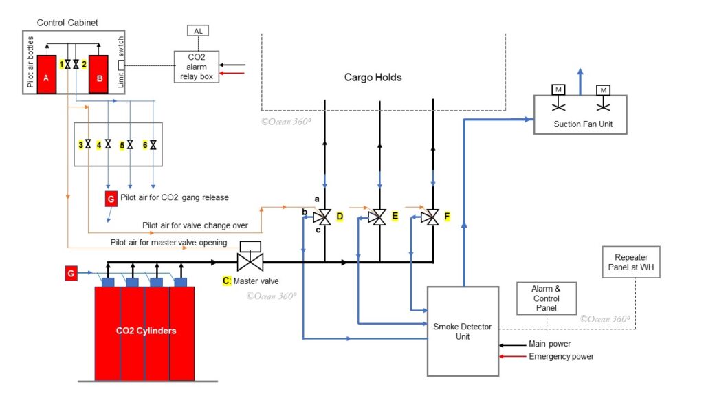
The figure below represents schematic diagram of a typical system installed on board.

Fig.1 CO2 flooding system for cargo holds
In reference to the Fig. 1.
In normal state,change over valves (D, E, F) are lined up for drawing sampling air from holds as indicated by the blue arrows.As an example,let’s take valve D – in normal situation valve port a & b are connected.At this position,suction fan unit continuously draws sampling air from the hold through the change over valve D,then deliver it to the smoke detection unit,and finally discharges to atmosphere.
In case of a fire in the hold sampling pipes from that particular hold will be filled with smoke.Smoke detection unit trigger an audible visual alarm and will indicate the hold in question.A repeater unit fitted at the wheel house will also generate alarm & indicate location of fire.Further,audible visual alarm will be activate in ECR and some other strategic locations as per the relevant regulation and requirement of the class.
To release first of all any one of the pilot air bottles(A or B) inside the control cabinet to be opened by operating the valve 1 or 2. This allows pilot air to reach the Master valve actuator.After that valve 3 to be opened,this will lead pilot air to Pneumatic change over valve (D) and change over the position of valve D,now valve port a & c will be connected as indicated by black arrows.Valve D is now ready to release discharge CO2.Note that at valve D previously a & b were connected.Similarly,corresponding valve to be operated to open pilot air to the Pneumatic change over valve(E or F) to change over the position of the form sampling mode to discharging mode,depending of the location of fire.
On completion of above sequence,valve 2 to be opened.This actuates cylinder valves of appropriate number CO2 cylinders and release CO2.
Liquid CO2 discharged from the cylinders will gasify immediately,and passing through the Master valve (C) & Change over valve(D/ E/ F),finally discharged into the cargo hold.
Hold fire detection system,the alarm system & CO2 release alarm system are powered by both the main power source and the emergency power source on board.
Emergency Release
In case of failure or breakdown of the system for remote operation,CO2 still can be released locally from the CO2 room.
As mentioned earlier,based on loading condition of the hold,first of all number cylinders of to be released for saturation to be determined from the chart provided by the maker/shipyard.
Afterwards,the Master valve (C)to be opened manually at CO2 room, this to be followed by manual changing over of appropriate change-over valve(D/E/F).
Finally,appropriate number of CO2 cylinders to be released by operating the manual actuators atop the cylinders.
–the end.